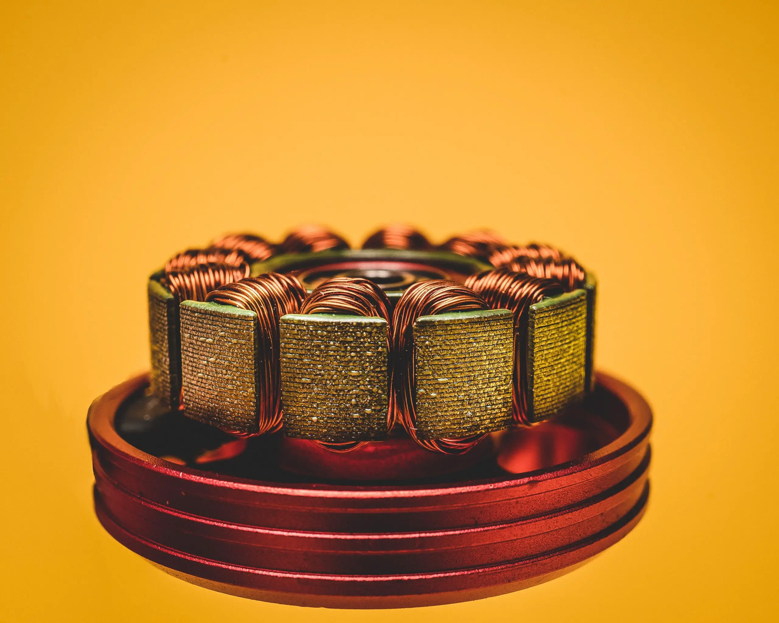
When a current flows in a wire, it creates a magnetic field around it. And, if the current-carrying wire is a coil, it creates a magnetic field that induces a voltage in it.
In other words, when the current-carrying conductor faces another magnetic field, it induces a force. And when a current-carrying conductor, moves in a magnetic field, it induces a voltage.
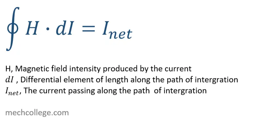
Magnetic field intensity around a closed path
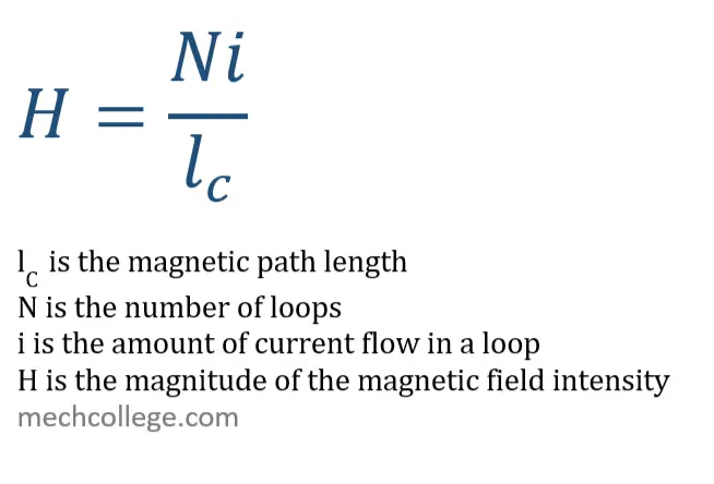
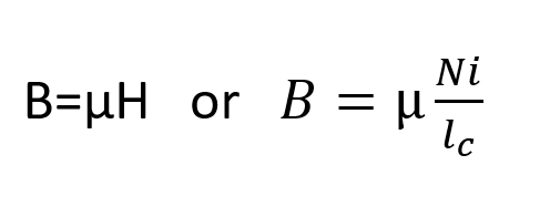
Magnetic field intensity H is the ability of current to create a magnetic field in a circuit. To calculate the magnetic field intensity, caused by a current, we can use the below equation, Ampere’s law.
If there is a ferromagnetic metal inside a coil, the magnetic field created by the coil is absorbed into the core.
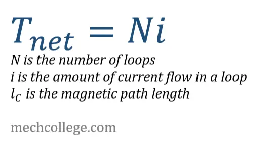
So, the Ampere’s law
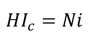
H is the magnitude of the magnetic field intensity vector,
Magnetic field intensity and the core
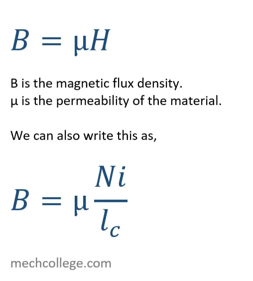
If there is a ferromagnetic metal inside the coil, the magnetic field created by the coil is absorbed into the core. However, the strength of the magnetic field depends on the core.
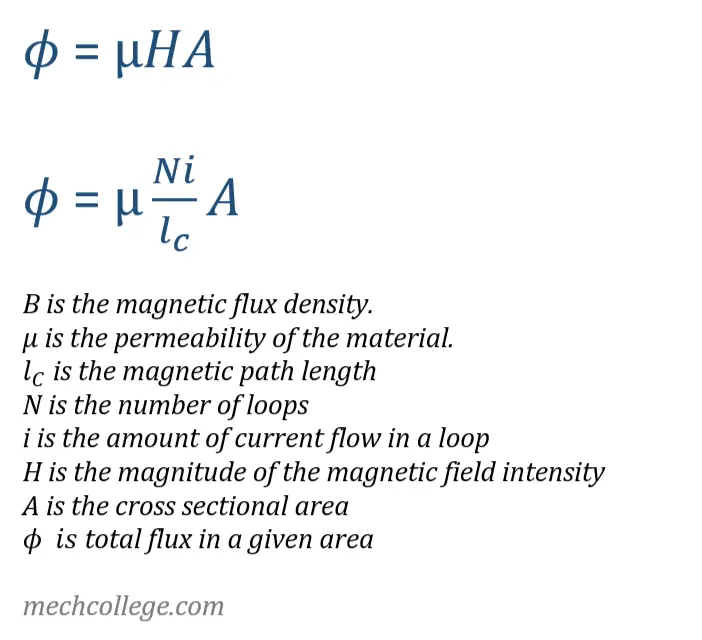
Total flux in a given area ϕ
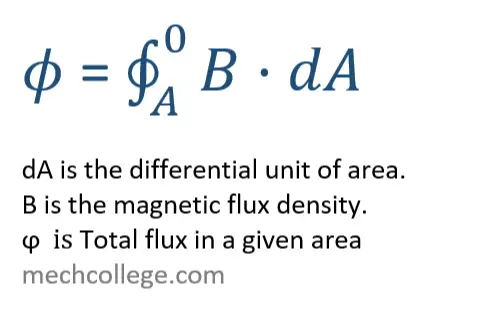
dA is the differential unit of area.
If the flux density is a constant and has a θ angle to a plane of area A, we can write the equation as,
ϕ =BA cos(θ)
If the flux density is perpendicular to the area and a constant, we can rewrite the above equation as,
ϕ = BA
So, to get to know the total magnetic flux generated by the current, we can substitute,
Into the equation, therefore the magnetic flux density,
Force that drives the current flow
In a normal electrical circuit, the voltage or the EMF (electromotive force) drives the current flow. So it can be described using Ohm’s law,
V=IR
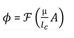
But in magnetic circuits, the force that drives the current flow is MMF (magnetomotive force). And it’s represented by the script letter F and measured by Ampere turns. The equation for magnetomotive force is,
F=Ni
So, we can write the magnetic flux as,
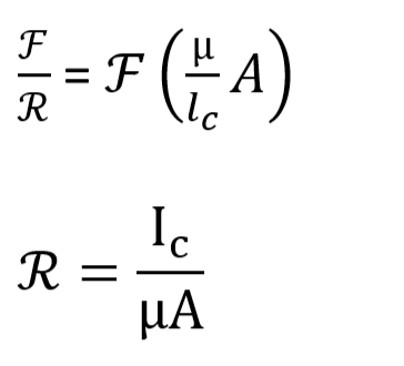
MMF, flux and reluctance
Magnetomotive force F (MMF) is the cause of the generation of magnetic flux ∅. Magnetic reluctance is a similar concept to electrical resistance. And the units of reluctance s ampere-turns per weber. Just like in Ohm’s law, we can build a relationship as follows,
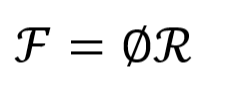
So, we can write the magnetic flux as,
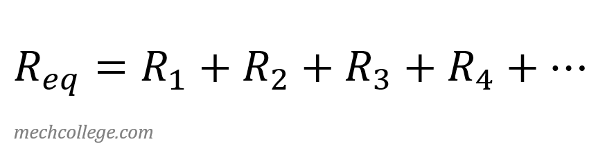
Reluctance in series
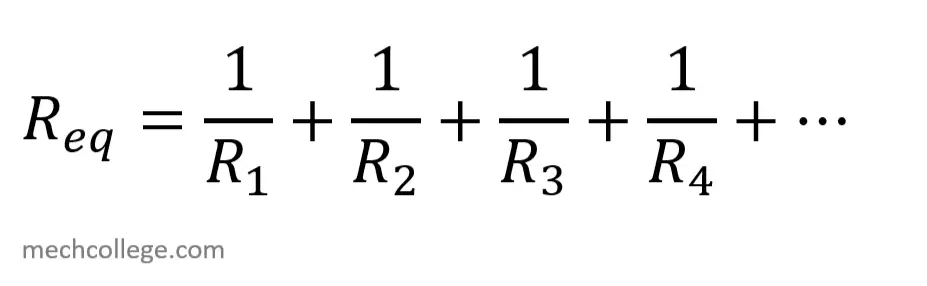
Reluctance in parallel
Permeance
As there is reluctance for the resistance, what is there for the conductance. There is permeance for the resistance.