SOLIDWORKS is a great software for designing 3D engineering models. To get the maximum effectiveness of the software, we have to manage the work space according to the project. In this article, we go through different tabs and windows of SOLIDWORKS to give you an understand about having the most effective works space.
In every software, the perfect workspace is a lie. So you’re frequently doing some certain type of projects, you better experiment different workspace arrangements using a timer.
Top Menu Bar
If you click the file icon over there, you can get the New SOLIDWORKS document window. Otherwise you can
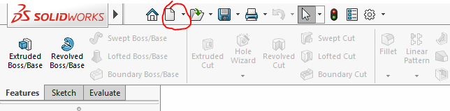
Otherwise you can click the arrow on the top, next to the SOLIDWORKS logo, and expand the menu bar. And go File > New.
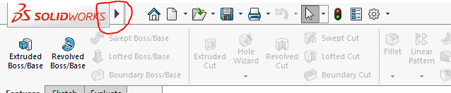
Once the menu bas is open you can see that there is a pin icon to the left. By clicking that icon, you can pin the top menu bar.
Or you can just use the shortcut command CTRL + N to open a New SOLIDWORKS Document. As you can see, the article goes in a flow, so you can make your required customization along this.
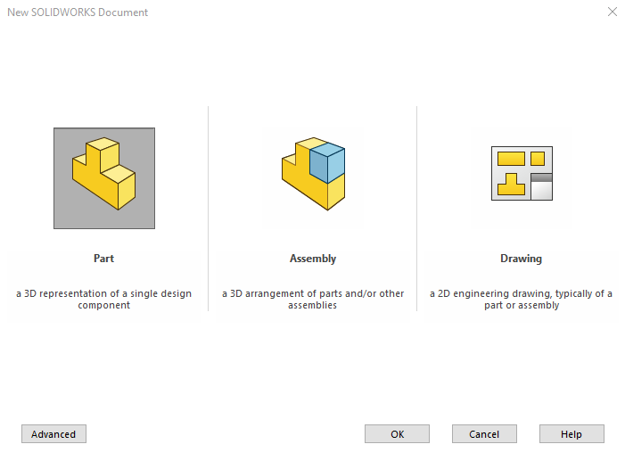
Once the New SOLIDWORKS Document tab opens, there will be three options. As you can see, SOLIDWORKS has three type of documents, with three types of environments.
Lets go with Part for now, Click on the Part and then click okay.
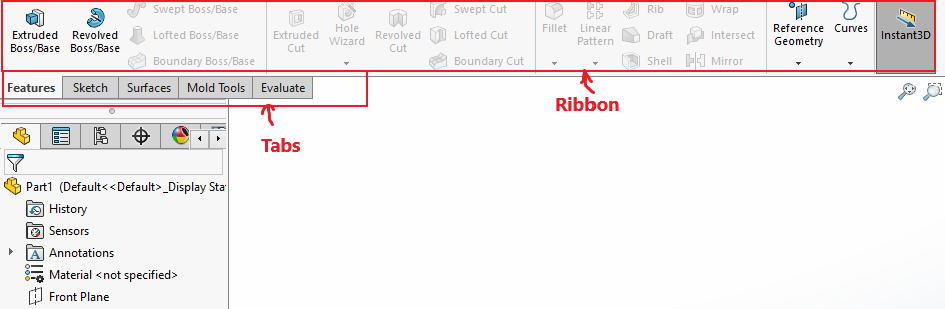
Tabs and Ribbons
Now check the tabs below the Ribbon. If you don’t know where the tabs are, check the image below. When you change the tab, you can see that the ribbon changes along with it.
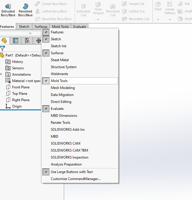
Now, you may see that there are more or less tabs in your SOLIDWORKS environment.
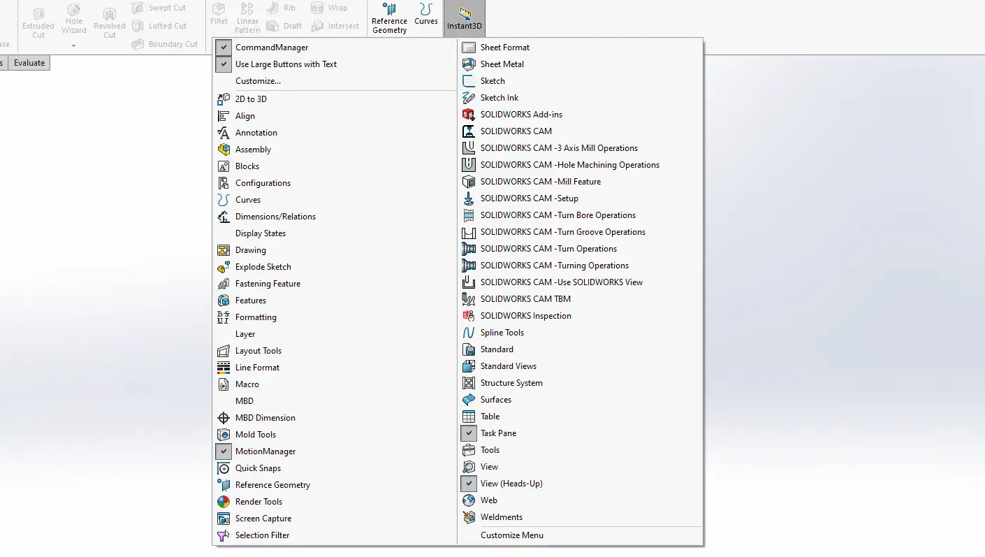
By right clicking on the tabs, you can easily select any tabs you want to activate or deactivate. For a higher productivity, it’s always good to activate only the required tabs for the job.
Toolbars
If you want on some toolbars, you can right click on the ribbon. And activate or deactivate any toolbar you want.
