The lathe machine is one of the most revolutionary inventions in mechanical engineering that lead everything to another level. It’s a fundamental machine in the metal industry and also used in the woodworking industry.
The workpiece is connected to a rotating shaft and a cutting tool is used to remove materials from the rotating workpiece. In this article, you will learn about different parts of the lathe and their functions.
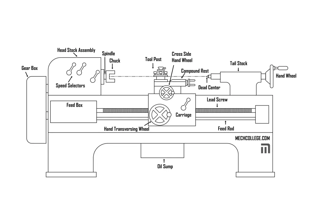
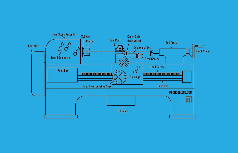
Headstock
The headstock of a lathe is the side where we fix the workpiece. So, it has the ability to supply power to the workpiece, And it’s consists of the speed selector, spindle, and chuck.
1. Spindle
The spindle, also known as workpiece spindles is used to provide rotational motion to the chuck and then to the workpiece. And it’s a shaft that is used to transfer power.
In a normal bench lathe, there are two spindles. One belongs to the headstock and the other belongs to the tailstock. So, each spindle is known as the headstock spindle and toolstock spindle.
2. Chuck
Chuck is a type of clamp that we use to hold the workpiece in radial symmetry. However, there are different mechanisms to clamp a workpiece in radial symmetry. As a result of that, there are several different chucks used in lathe machines. And those are as follows.
- Three jaw chuck: to hold round and polygon shapes (easier than four jaw chuck)
- Four jaw chuck: ideal to hold irregular shapes since it’s more flexible, and also work with different polygon shapes
- Collet chuck: to hold tools and workpieces (tighter clamping)
- Hydraulic chuck: To hold tools and workpieces more precisely.
- Pneumatic chuck: Ideal to hold pipes
- Drill chuck: To drill the workpiece
- Magnetic chuck: to hold the workpieces with short length but large diameters
3. Speed Selector
As the name suggests, the speed selector is used to control the rotating speed of the workpiece. Since the spindle is directly connected to the chuck and the workpiece is directly connected to the chuck, the speed of the workpiece is the same as the spindle speed.
Tailstock
Tailstock provides support to the workpiece along the center of rotation. And it’s located on the opposite side of the headstock. And the toolstock consists of a few components.
- Tailstock spindle
- Tailstock handwheel
- Tailstock spindle lock
Bed
The beam is a base structure of the lathe that supports all the major components of the lathe including the headstock and the tailstock. In metal lathe machines, the bed is built using metals and most commonly using cast iron.
Carriage
Carriage is used to feed and to change the angle of the tool according to the requirements. It’s located between the headstock and the tailstock. And there are two major components in the carriage.
- Saddle: H shape structure and supports cross slide movements
- Apron: To control the feed
Lead Screw
The carriage needs power from the operator, so we use the lead screw to transfer power from headstock to carriage. Since it’s used to transfer power, it’s also called a power screw.
Moreover, the headstock has rotational motion and also the lead screw. And then it’s transferred into a linear motion.
The lead screw is used for screw thread cutting operations.
Feed Rod
The feed rod is used to transfer power to the carriage just like in the lead screw. However, we can’t use the feed rod for thread cutting. So, it’s used to feed the carriage and the cross slide.